Rosy, a restoration project - The rolling chassis

Chassis ...


When I had removed everything from the chassis and had it pressure washed and shot blasted, I painted it with a zinc based primer undercoat to keep away any further rust.  I checked the chassis for alignment by the simple expedient of measuring with a tape measure all the distances from one side of the chassis to the other and across the corners and found they all measured the same, so I was happy that the chassis was straight.

The chassis painted with zink based primer


As the chassis itself was reasonably sound, although with some corrosion, I did not believe it warranted any of the chassis cutting out and replacing.  I then painted it with chassis black paint, I was thinking of having it powder coated or even stove enamelled but as this was not done to it when it was built in 1937, I decided that what was good enough for MG was good enough for me.  It has lasted for 67 years like this so my liberal coating of several coats of chassis black paint should see it OK for another 67 years.

The trunnion replacements (f), the spring reconditioning (e), the rebuilding of the shock absorbers (c), the re-spoking of the wheels (i), the reconditioning of the brake cylinders (d), the purchase of two new wheels (a) and the rebuild of the differential assembly, etc. is written about in later text.


Trunnions ...


The first problem.  When I had stripped everything off the chassis I was left with the rear trunnion assemblies. When you are not sure how to go about stripping something it is sensible to look in the "Blower" manual for advice, but when you are faced with a simple hexagon nut to undo, who needs "Blowers"?

The photograph below shows the wrecked trunnion when I resorted to brute force when I thought the threads were normal right hand threads!  No they are not!  They are left hand threads, and I burst the cross tube of the chassis when applying excessive force.  Fortunately I was "lucky" in that they were worn and needed replacing, when it had had a previous overhaul and correct parts were not readily available the trunnion assembly had been "modified",  I would not use the word "bodged" as it was an engineered answer to a problem.  The probable reason for the threads being left hand is in the manufacture of the hexagon nuts.  As these parts were made on ordinary lathes without the benefit of modern CNC technology, it is easier to start the thread from inside the undercut of the hexagon nut and chase the thread outwards than trying to trip the feed inside the undercut if it were a right hand thread!

wrecked trunnion
The trunnions have left hand threads!

I had positioned the replacement trunnion assemblies perfectly in line and the correct distance out from the chassis and had them welded into position. On coming to assemble the springs and trunnions the first problem I encountered was that having had the springs "reconditioned" I found that they had linished the wear off the 1/4" thick spring that goes through the trunnion bushes. As a consequence they were quite loose (to put it politely) to be of any use. So back to the spring company they went, showed them the problem and they made new 1/4" leafs for the spring assemblies, now they fit perfectly, why couldn't they have got it right first time? What do they say about three paces forward and two paces back?

I now came to fit the springs into the machined slots in the trunnion tubes into the perfect fitting trunnion bushes, I now came to try and fit in the spacer, with peg on it to stop it rotating and guess what? They do not fit, the 1 1/16" diameter that these spacers fit in, It had not been machined! At this point I said a short prayer and called it a night. Phone up the supplier Monday morning to see what he has to say!

He had the answer, they believed that it would be stronger to leave the 1" diameter to run through for strength, and had they forgotten to send me the 1" spacing piece to replace the original 1 1/16"?  Yes they had, so they were despatched that day and I received them the next! Another problem sorted.


Silentbloc bushes ...


siezed bush
The removed bush

The next problem I encountered on the strip down of the chassis was the Silentbloc bush on the offside of the chassis. When I had thought I had completely stripped the chassis, I had noticed on the outriggers where the rear springs fit, on to what I now know to be Silentbloc bushes, that there was a discrepancy in the diameters on the pins that the bushes fit on. I eventually realised that the discrepancy in diameters was that the inner bush of the assembly had seized up on the pin. It did not want to come off, after up to 65 years on the chassis it fought its removal every inch of the way. (In this mad world of political correctness I suppose I should say every millimetre of the way, but you know what I mean). It refused to be knocked off with a chisel, so after drilling several holes and hack-sawing across the holes and judicial use of the chisel I split the bush and finally managed to remove it from the chassis!

Having worked out which shock absorber, complete now with new bushes, went to front and rear, I proceeded to fit the shock absorbers on to the chassis.  When I stripped the car down, one of my earlier thoughts was make a record of where everything fitted.  I did not, as I thought it would be obvious which way they fitted, no way, if they can be fitted wrong they will be fitted wrong.  However reading the excellent publication T Series Restoration Guide by Malcolm Green I found the answer.  As there is no weight on the springs the back axle assembly will need to be pulled down on to the buffer stops.  That is if I could pull them down on to the spring assembly, when the company I entrusted to renovate my springs returned them to me I have already told you of one problem, I now found the second.  The springs are clamped together with two plates held together with two ¼" BSF studs.  As one was broken they drilled out the broken stud and replaced it with two 6mm hexagon head set screws, to balance it out they had done this to the other side as well!  Having now realised that was one reason why I could not fit the back axle I set about rectifying the problem.  I had the holes welded up and making sure I could still get ¼" BSF Wire I drilled and tapped the holes out and fitted "replacement studs".  Now it fits together.


Differential gear ...


The next part to fit is the differential assembly that has been rebuilt by Roger Furneux and he demonstrated what had been done to it by using it as his example in the recent T Register Workshop Day at St Neots.

The photographs shows both the differential assembly and the replacement plate welded onto the axle assembly where the stress causes the metal to split.

differential gear
Differential gear

replacement plate welded onto the axle assembly where the stress causes the metal to split
Repair to axle assembly

Brakes ...


Now I am involved in getting the braking system operational again, the first decision is do we use or try to use any of the old brake pipes?  No!  That has sorted that out, the brake pipes, that is the copper ones and the three flexible hoses are all showing their age, so all are to be replaced.  Having had a look at the set the Octagon Car Club are offering I realised that some of the ends were different to mine, i.e. female ends where I expected male ends and vice versa, so a new set are being provided and when I have them I will check them against Flivver.  Ken will have it correct, I feel sure.

Early MG TA Brake Fittings and Pipes

This part is for those of us that have the early type TA's, that is those with the narrow wings and wide tank.  I will not attempt to give the chassis number that this information applies to as I am not sure myself.  However my chassis numbers are 0418 and 1237 and as the piping and fittings are identical on these two cars then it should be a safe bet that all of the cars between these chassis numbers should be the same!

The reason for including this note is that brake pipe sets provided by some suppliers are not “apparently” correct, that is the pipes have the wrong ends for the application they are required for.  So here is my version of the pipes and fittings for these early TA's: All of the pipes and therefore the fittings are of the flared type and are not compression fittings!

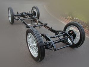
Starting from the master cylinder there is a fitting 6372/4 that is screwed into the rear of the cylinder and has two female outlets.  The outlet facing out from the chassis is connected to the front offside brake cylinder flexible pipe via a pipe 40" long with a protective coil around it for the whole of its length.  The outlet facing into the chassis is connected to the male 3-way connector 6020/4 that is bolted to the nearside chassis via a pipe 29" long with a protective coil around it for the whole of its length.  The forward outlet goes to the front nearside brake cylinder flexible pipe via a pipe 30" long with a protective coil around it for the whole of its length.  An interesting observation here is that the nearside pipe goes through a hole in the chassis so only a short length of the pipe is observed from the outside, whereas the offside one does not.  I can see no reason for it not going through the chassis and it would clear the wheel easily when a full lock is applied, mine just touches the brake pipe on full lock.  The final rear facing male part of connector 6020/4 is connected to the flexible pipe fitting on the cross member by the differential via a pipe 74" that has no need to be protected by an armoured coil as it is routed via the inside of the chassis rail.

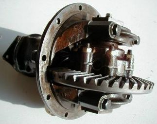
The flexible brake hose from the cross member then goes to a 3-way connector 241/4 that is bolted to the differential.  This fitting is a female, male, male fitting, the flexible hose is screwed into the female thread and the other males are for the two rear brake connections.  The one to the rear offside is 16" long and protected by an armoured coil for the whole of its length and the one to the rear nearside is 29" and again protected for the whole of its length by an armoured coil.  Both of these pipes are screwed into the rear brake cylinders by a banjo fitting 2949/4, this means that to fit the banjo fittings the pipes must have a male fitting to go into the female banjo fitting and consequently the other ends have a female nut on them.  Incidentally both of these pipes run to the rear of the rear axle straps not inside as they would be crushed if you gave the suspension a true test of its capabilities.

If anyone knows of any mistakes in this section of the text would they please let me know so I can make the neccessary corrections.  I can also put right any faults that I may have transferred to my rebuild project TA 1237.